UPDATE: There is a more recent article with shorter instructions.
UPDATE: Now that a few other people are experimenting with the Arduino-based controllers, I have put some further thoughts at the bottom of this post. If you have any questions, feel free to ask, either in the comments here, or in the comments on my Facebook post, or you can easily find my email address by googling.
There's a lot of ringing going on over the internet. Some people ring by pressing keys on the keyboard, but others use Graham John's Handbell Manager to enable ActionXL motion controllers to be used as dummy handbells. Handbell Manager converts the up/down motion of the ActionXL into keypresses which can be fed to Abel, Ringing Room or anything else. Graham John's Handbell Stadium platform requires the use of motion controllers and doesn't allow ringing by keypresses. This is a deliberate design so that ringing on Handbell Stadium replicates as closely as possible the normal experience of handbell ringing. It's possible to use the ActionXL directly as a dummy handbell, which is what I have been doing, but it feels better if you add some weight. Some people attach the ActionXL to a heavy object such as a spanner. Others attach it to the handle of a real handbell, with rubber bands, and then either tie the clapper (like silencing a tower bell) or unscrew the clapper altogether.
The story of the ActionXL controllers, as told by Graham, is that only one batch was manufactured. Graham started using them about ten years ago, which is when I bought my set. At that time they could be bought from Amazon. They were intended for PC gaming, but apparently there wasn't really a large market. Graham has been in contact with the producer, in the US, and at some point he bought most of the remaining supply and has been selling them from his home. I think they are all gone now, and the ones that the producer kept have probably also been sold to American ringers, so basically it's not possible to get hold of them unless you can find them secondhand on eBay.
I wondered about using a hobbyist computer board such as a micro:bit to make a motion controller. My daughter Dorothy has one, which we've done a few projects with. It has an accelerometer built in, which is the key component needed for the motion sensing - it enables the orientation of the device to be measured, and then Handbell Manager or Handbell Stadium trigger the bell to strike when the device moves to the appropriate angle, upwards or downwards.
Recently I have been involved in a lot of discussion about Handbell Stadium, with some test ringing that I have written about already. Some of the discussion included Richard Johnston (of mini-bell fame) who pointed out that making a device behave like a game controller (such as the ActionXL) when plugged into a USB socket requires a particular kind of USB interface, which the micro:bit doesn't have. However, some further research showed that it is possible with an Arduino, which is another hobbyist electronics system, and many people have used Arduino boards to make game controllers.
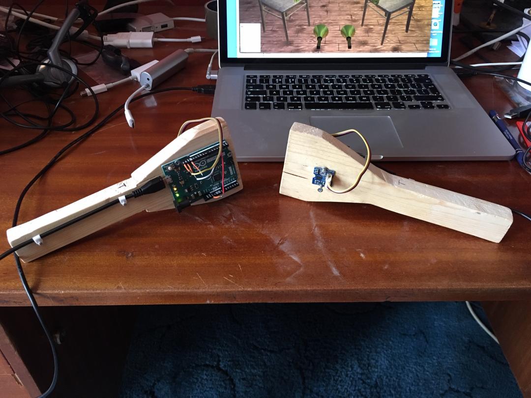
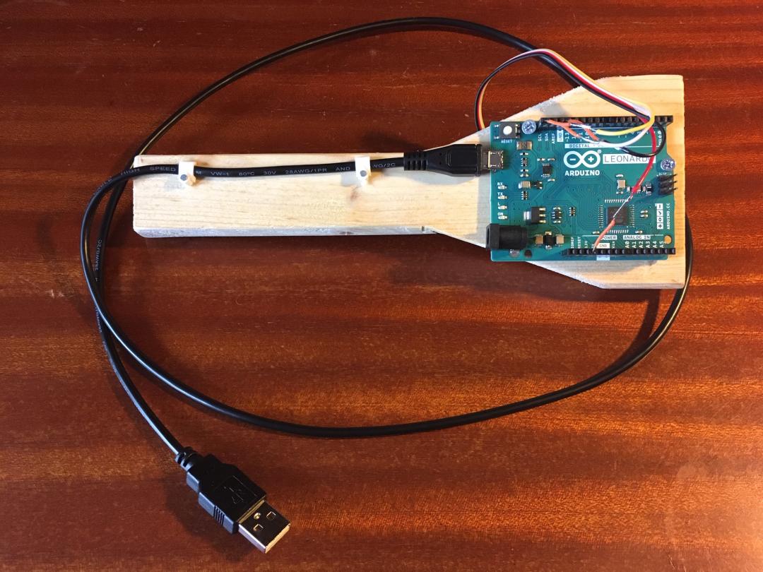
Yesterday Dorothy and I made two prototype handbell controllers based on Arduinos. They work well with Handbell Stadium. They don't have the little buttons that the ActionXL has, which can be used to start and stop the ringing when using Handbell Stadium or Abel in solo practice mode. But for ringing with other people that's not necessary - and in any case it would be easy to add buttons later. They are based on an Arduino Leonardo (the large board) and a Grove 3-axis digital accelerometer (the small board). The handbell shape is made from scrap wood, proving yet again that you should never throw anything away. Once the necessary software has been installed on the Leonardo, the controllers just plug into a USB socket and work immediately with Handbell Stadium or Handbell Manager.
I will now describe how we made the handbell controllers. This is a simple design that doesn't require electronics expertise or soldering. If you don't mind doing some soldering, then it's possible to reduce the cost. There are three aspects: the electronics, the software, and the dummy handbells.
The electronics
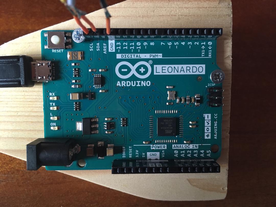
The main component is an Arduino Leonardo with headers. The headers are little sockets that enable wires to be plugged in without soldering. If you don't mind soldering, then a board without headers is slightly cheaper, or you can use a Leonardo Pro Micro which is smaller and much cheaper. There are many varieties of Arduino, but for the handbell controllers it's important to use a Leonardo because of the way its USB interface is configured. (I have come across other projects that use different Arduinos and replace their USB configuration firmware, but that seems more complicated).
I bought the Leonardo from the Arduino store for €21.60, which meant that it had to be delivered from Italy. If you are in the UK, it's probably more convenient to get it from RS for £18.36. Other suppliers are available. There are some very cheap ones on eBay, but they tend to be shipped from China with much longer delivery times.
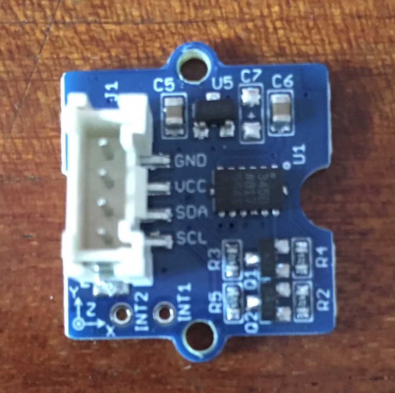
The other key component is the accelerometer. We used a Grove 3-axis digital accelerometer, which was €11.40 from the Arduino store. Again there are other suppliers, for example (in the UK) Okdo for £9.06. Again you can find a version slightly cheaper without the socket, if you are into soldering. There are many other accelerometers that can work with the Arduino. The software I'm going to describe later is specific to the AXDL345 chip in the Grove sensor, but I'm sure it can be adapted for other components.
The Grove accelerometer comes with a little cable that has plugs on both ends. This isn't quite what you want. I cut one of the plugs off, and then had to solder some little solid-core wires onto the bare ends so that they would plug nicely into the header sockets on the Leonardo. A better way is to buy a "Grove 4 pin Male Jumper to Grove 4 pin Conversion Cable" which comes in a pack of 5 from Cool Components for £2.83. I have ordered some and will update my wiring as soon as they arrive.
Finally, you need a USB cable. One end needs to be "micro type B male" to plug into the Leonardo. The other end should be either USB or USB-C to suit your computer. I bought the USB cables from the Arduino store with everything else, where they were €3.48, but you can find a more convenient supplier. It's worth getting fairly long cables. The ones I bought say they are 1.8m, but I'm not convinced. The ActionXL cables are closer to 2m, which sounds long but you want to be able to sit far enough away from your computer so that the dummy handbells don't get caught on the table.
To connect the accelerometer to the Leonardo, match up the pin names on the two boards. The Grove cable has black, red, white and yellow wires. Black is ground (GND) and it plugs into a GND socket on the Leonardo (on mine there are 3 GND sockets to choose from). Red is the power supply. The accelerometer can work on either 3.3V or 5V. I plugged it into the 3.3V socket on the Leonardo. The other two wires are called SDA (white) and SCL (yellow), which are serial data and serial clock. They plug into sockets of the same name on the Leonardo. Finally, plug the Leonardo into your computer with the USB cable.
The software
For this stage, it's useful to have some familiarity and confidence with downloading and installing software. It's difficult to describe exactly the steps required. To upload software onto the Arduino, you can either use the Arduino Create web-based system or install the IDE (integrated development environment) on your computer. I have had better results with the IDE. When you have set it up, you need to add the Joystick library. To do that, use the "clone or download" button in the GitHub page to download the ZIP file. If you are using the IDE, put the whole unzipped folder ArduinoJoystickLibrary-master into your working folder for Arduino projects. Then you need this code as your main program:
/*
 * Software for the Arduino Leonardo with an ADXL345 accelerometer.
 * Based on the tutorial by Dejan at https://howtomechatronics.com
*/

#include <Wire.h> // This is a standard Arduino library - used for I2C communication with the ADXL345 and other devices

#include "Joystick.h" // This library has to be installed

Joystick_ Joystick;

int ADXL345 = 0x53; // The ADXL345 sensor I2C address

float x_axis, y_axis, z_axis;  // The values received from the ADXL345

void setup() {
  // Initiate the Wire library
  Wire.begin();
  // Set ADXL345 in measuring mode
  // Start communicating with the device
  Wire.beginTransmission(ADXL345);
  // Access / talk to POWER_CTL Register - 0x2D
  Wire.write(0x2D);
  // Enable measurement
  // (8dec -> 0000 1000 binary) Bit D3 High for measuring enable
  Wire.write(8);
  Wire.endTransmission();
  Wire.beginTransmission(ADXL345);
  Wire.write(0x31); // Set the measurement range
  Wire.write(0); // Set 10-bit mode with range -2g..+2g. We should now find that values are in the range -512..+511
  Wire.endTransmission();

  // Handbell Stadium just uses one axis, which can be set to X, Y or Z
  // This can allow for mounting the accelerometer differently on the dummy handbell
  Joystick.setXAxisRange(-512, 511);
  Joystick.setYAxisRange(-512, 511);
  Joystick.setZAxisRange(-512, 511);
  // Set up the Joystick. false means that data is not transmitted automatically.
  Joystick.begin(false);
  delay(10);
}

void loop() {
  // === Read accelerometer data === //
  Wire.beginTransmission(ADXL345);
  // Start with register 0x32 (ACCEL_XOUT_H)
  Wire.write(0x32);
  Wire.endTransmission(false);
  // Read 6 registers total, each axis value is stored in 2 registers
  Wire.requestFrom(ADXL345, 6, true);
  x_axis = ( Wire.read()| Wire.read() << 8);
  y_axis = ( Wire.read()| Wire.read() << 8);
  z_axis = ( Wire.read()| Wire.read() << 8);

  // Store the axis values in the Joystick.
  // This takes care of mapping the values into the -800..800 range.
  Joystick.setXAxis(x_axis);
  Joystick.setYAxis(y_axis);
  Joystick.setZAxis(z_axis);
  // Send the joystick data to the PC.
  Joystick.sendState();
  // Short delay - data will be sent every 10ms
  delay(10);
}
If everything is set up correctly, this code can be uploaded to the Leonardo. If you try this and have problems, write a comment and I will try to help.
After uploading the code to the Leonardo, you can start Handbell Manager or Handbell Stadium and see the effect of moving the accelerometer. Within either software, you can choose which accelerometer axis controls the striking of the bell. The way I mounted the accelerometer on the dummy handbell, it ended up being the Y axis, but you might do it differently.
The dummy handbells
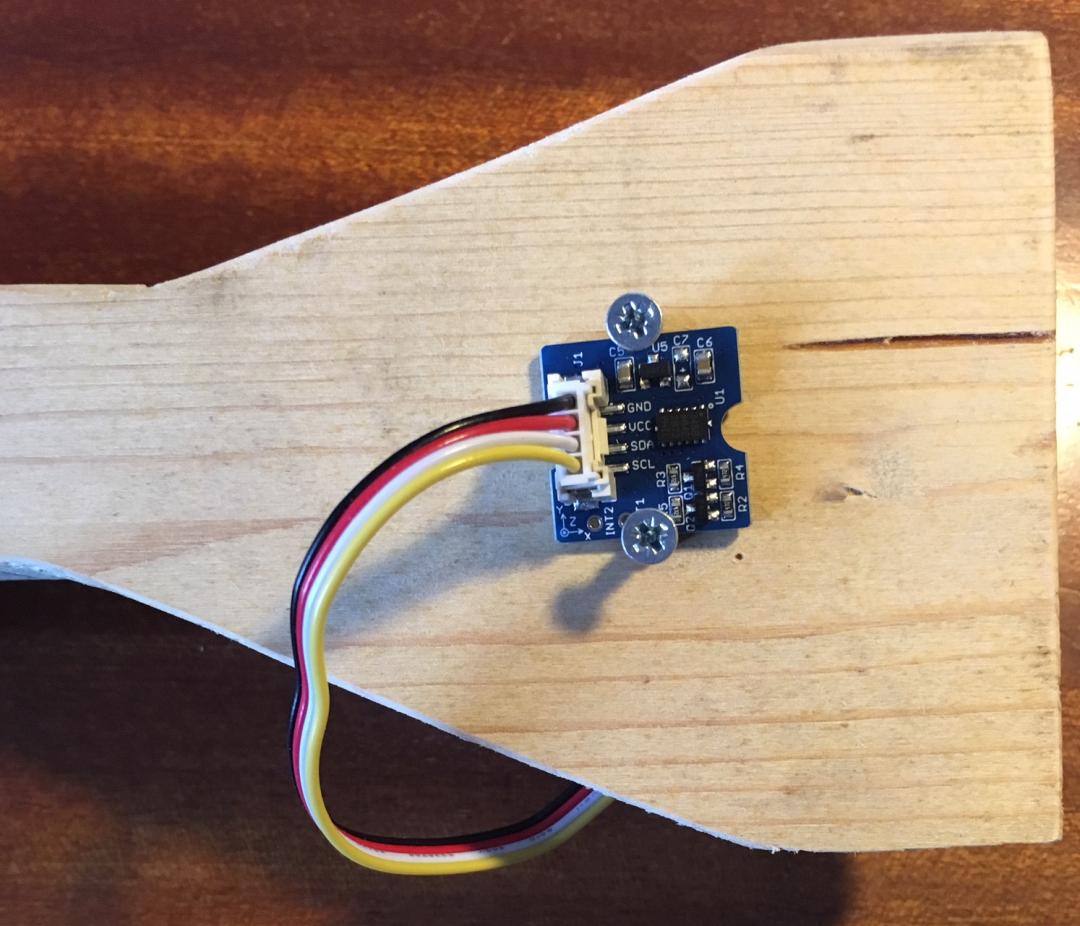
We marked out a simple handbell shape on a piece of scrap wood and cut it out. The Leonardo is screwed to one side (picture above) and the accelerometer is screwed to the other side. The screws here are far too big; I have ordered some smaller ones. Notice that the socket of the accelerometer is pointing towards the handle of the handbell shape. The orientation works with the program shown above. If you put the accelerometer on the other side of the handbell shape, next to the Leonardo, you might have to experiment with its orientation and possibly adapt the code. Ask in the comments section if you need advice.
These dummy handbells are very basic, but they already give a better ringing feel than the plain ActionXL controllers. Adding a bit of weight would make them even better. I am thinking of using plastic flowerpots to cover the electronics and make a 3D bell shape. Graham John suggested using badminton racquet tape around the handle to improve the feel - I have ordered some and will try it. That made me think of using a table tennis bat as the dummy handbell. You would get a nice comfortable handle, and a large flat surface for mounting the electronics and maybe some weight. There are all sorts of possibilities.
Further thoughts (7th June)
- If you want to avoid soldering, stick to the Arduino Leonardo and the Grove accelerometer unit.
- If you don't mind soldering, a Leonardo Pro Micro is smaller and cheaper. Also an MPU6050 accelerometer unit is cheaper than the Grove unit. You can find both of these on eBay, but make sure the supplier is based in the UK. The very cheapest ones are shipped from China, which takes a long time.
- The Joystick library that I used is not the one that you find in the standard list of available libraries, within the Arduino software development environment. Download it from the GitHub link that I showed above. Probably you can use the Joystick library from the standard list instead, but I haven't tried that.
- At the time of writing, there is a glitch in Handbell Stadium that you need to compensate for in the code that you put onto the Arduino. Ideally what you should be doing is programming the Arduino to send its X, Y and Z axis values - that's what the code shown above does. The axis value that's needed for handbell ringing depends on how you have mounted the accelerometer on your dummy handbell. For me it's the Y axis. By default, Handbell Stadium and Handbell Manager use the Z axis, but they have options to use a different axis, so you can just set it to Y. BUT in the currently released version of Handbell Stadium, these options don't work. To compensate for that, you need to adjust the code on the Arduino so that it has the line
Joystick.setZAxis(y_axis);
Handbell Stadium will be fixed soon, and then this problem will go away. - I have updated the code shown above a little bit, to properly set the range of values that the accelerometer is measuring in.
- I wrote that everything works with Handbell Stadium and Handbell Manager, but I haven't tested it with Handbell Manager because I only have it on an ancient Windows laptop that is barely working. If you are using Handbell Manager, you might need to make further adjustments to the range of values. I believe that the ActionXL controllers use the range -2048..+2047. Contact me if you need advice.
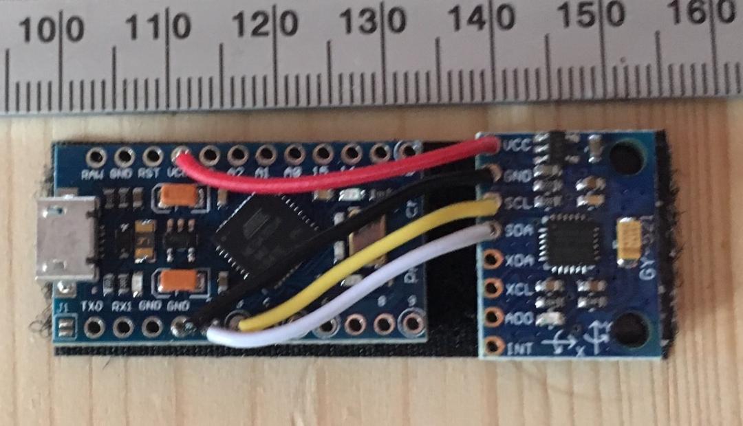
Here is the latest version: an Arduino Leonardo Pro Micro and a GY-521 accelerometer board (based on the MPU6050), mounted on sticky-backed velcro.